Exposure Latitude: typically your black and white negative films have the most film latitude before whites get whiter and darks stay darker, about 7 stops. Color negative films generally chime in about 5 stops. Color reversal (slide) films step in at about three-four stops. Closer to three.
Exposure Latitude:
You can get the information you are seeking by looking at the characteristic curves in the film spec sheets. I've attached the curve of Velvia 50. Looking at the linear part of the curve, it spans roughly 1.25-1.5 log exposure, which corresponds to 4-5 stops. Each .3 of log exposure is a stop. Of course you get a little extra density in the shoulder and toe, but it's non-linear there, so think of it as a bonus - I wouldn't put any important detail there. But it still would probably let you get some detail in another stop or so, mostly in the toe region, which corresponds to highlights.
Also I've similarly observed with average metering:
The exposure latitude of color slide film is approximately -1-1/2 to +1/2 stops. With color print film, it's about -1-1/2 to +3 stops--and even +4 stops can give decent results. Digital capture generally has an exposure latitude of about -2 to +2/3 stops without enhancement. General rule: Err on the side of underexposure with slide film and digital, and on the side of overexposure with color print film
The purpose of
preparing this addendum is two-fold: to try to make it easier for
photographers to grasp the basics of this way to control the view
camera, and to describe a few refinements to earlier ideas.
Probably the most
widely used.
Offers an accurate tone range in compensating for the blue sensitivity
of panchromatic films. Will slightly darken sky and increase
contrast
between blue sky and clouds. Also may help reduce haze.
Yellow,
Chartreuse, Olive, Red,
Pink, Orange, Lime Green
Blue, Violet,
Purple, Lilacs
Deep Yellow 15 (O)
2.5x
+1 1/3
Stronger effect
than medium yellow.
May darken sky considerably
Yellow,
Chartreuse, Olive, Red,
Pink, Orange, Lime Green
Blue, Violet,
Purple
Red 25 (A)
8x
+3
Produces very
dramatic skies.
Effects may border on the surreal. Darkens foliage. Reduces haze.
Reds, pinks,
magentas, some browns,
yellow, orange
Blues, greens,
cyan
Green
11***
4x
+2
Lightens foliage
and will darken
skies somewhat. Sometimes used to produce pleasing skin tones in
portraits
Yellow,
yellow-green, olive, greens
Blue, violet,
magenta, red, maroon
UV
1x
0
Absorbs UV
radiation and will reduce
distant haze or fogginess
Polarizer
2.5x
+1 1/3
Helps remove reflections and glare.
May cut pollution
haze. Darkens sky.
Grad ND
n/a
n/a
Reduces the amount of light reaching a part
of the image
-- usually used to darken the sky.
*The correct title
probably should
be "The Filters I Usually Carry in the Field". **The numbers such as
"Red
25" are Kodak designations. These filters may be assigned
different
numbers by other manufacturers. I have included some other common
designations such as "K2". ***For some lenses I
have
a darker version called Green 58 instead of the Green 11. It
requires
3 stops extra exposure.
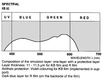
EFKE FILM TECHNICAL DATA
25-Feb-11 02:43 PM: EFKE FILM TECHNICAL DATA
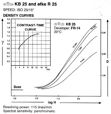
Efke KB25 and R25 Film
Efke KB50 and R50 Film
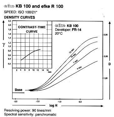
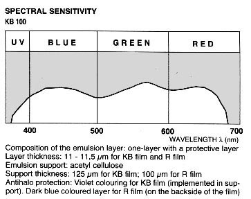
Efke KB100 and R100 Film
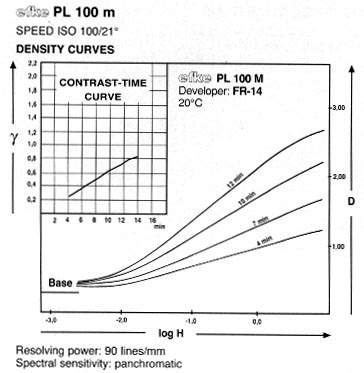
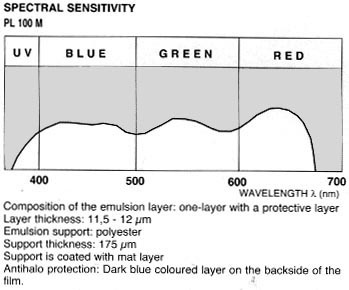
Efke PL100 Film
Notes:
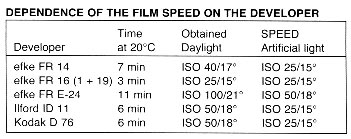
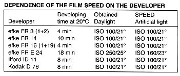
1. The reference developer used for the D log E curves is efke FR-14, a general purpose developer similar to Kodak D-76 and Ilford ID-11.
2. efke FR-16 is a universal type developer for films and papers
3. efke FR E-24 is a high speed low grain type of developer
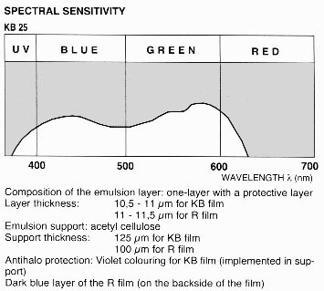
4. Overexposure is not recommended with efke films. This is due to the single layer structure of the film, which produces light scattering if overexposed. For best results expose the films either at nominal or higher speeds.
5. The plates above reference a "cellulose emulsion support". This is for the older efke films which have a grey-coloured base. If you have an efke film with the dark blue-green coloured base, this is the newer polyester support. This support is extremely strong and can damage your film winding sprockets if you wind past the length of the film. It is recommended to use only the older cellulose support films if you intend to attempt winding past the end of the film.
I just wrote this to someone else and feel like I should have this somewhere for good.
Here is how I do things.
I (spot)meter the shadows and then I (spot)meter the highlights.
If there is a 7 stop difference: -2 development If there is a 6 stop difference: -1 development If there is a 5 stop difference: Normal Development If there is a 4 stop difference: +1 development If there is a 3 stop difference: +2 development
Now for developing the film: I have my own times for Normal. -2 developing is 40% less time than Normal -1 developing is 20% less time than Normal +1 developing is 20% more time than Normal +2 developing is 40% more time than Normal
The ZS tells you to expose for the shadow and develop for the highlight. This is how you do it.
Now for the rest of the fun stuff.
Slow films such as FP4+ and Pan F+, I use at 1/3 stop more exposure, meaning I shoot FP4+ at 100 and Pan F+ at 40. Then I develop normally in Rodinal using Ilford times.
For faster films like HP5+, I shoot at box speed and develop in xtol using Ilford times.
Then I apply my +/- calculations as shown above.
If I shoot a sheet or roll of FP4+, I set my meter at 100. I meter the shadows at it gives me a number (I use EV's). Then I meter the highlights. If the difference is 6 stops, then I take 20% off my normal developing time.
My normal developing times are what the film manufacturer tells me. So for Ilford FP4+ in Rodinal 1+50, then Normal time is 15 minutes at an iso/asa of 125.
So, here are my times for Ilford FP4+ in Rodinal 1+50 Normal = 15 minutes N-1 = 12 minutes N-2 = 9 minutes N+1 = 18 minutes N+2 = 21 minutes
The Zone system, as used in black and white photography, is a refinement of the old "Expose for the shadows, develop for the highlights" adage. It is more concerned with determining the correct film development than with the correct exposure. ("Correct" in this context is a subjective term)
Once you can "see" and understand what happens to film when it becomes developed, the Zone system becomes clear. Let's pretend that you take a picture of a black square next to a white square (black square on the left) on a sheet of film. Let's also pretend that you can see the film as it develops (pre-fixed and everything.)Place the film in the developer and what do you see? The black square is already there! Remember, this is a negative, the black square will show as clear and the white square will show as black when the negative is fully developed. After about a minute or so, you start to see a light gray square starting to form on the right side of the negative. After 2 or 3 minutes it will get darker and darker. The longer you have the film in the developer, the darker it will get until it appears pure black. (and hence will print pure white) What happened to our square on the left? Nothing. It was going to show as a clear square on the developed film (so it would print pure black). That's the way it started out and that's the way it ended up. The silver halides of the emulsion were not "triggered" by light on the left side so the developer did nothing. Increasing or decreasing development time can only change the highlights, never the shadows.
CHART
From the above chart, it can be seen that over or under development does not affect the blacks but will lighten or darken the whites. If my spot meter indicates that normal development will cause my highest whites to fall on Zone VII (light gray), I will over develop to push them up to Zone IX, if I want them to be brighter. If my whites were going to fall on Zone X or higher (pure white, no texture), I would underdevelop to pull them back down to zone VIII or IX, whichever I desired.
There are many different ways to achieve N+1 or N+2 or N-1 or N-2 etc. I prefer to just alter the development time.I use Plus-X or Tri-X films. These may not be wholey accurate but they work fairly well for me:
N-1 = 25% decrease in development time
N-2 = 50% decrease in development time (never go beyond a 50% decrease) I actually do about a 40% decrease.
N+1 = 25% increase in development time
N+2 = 50 % increase in development time.
Many books call for about a 20% factor for Plus-X and 30% for Tri-X but I split the difference and use that 25% for both. Low speed films should be about 15% factors.
I do not recommend the use of T-Max films with the Zone system for beginners. It has been my experience that changes in the developing times have a far greater effect than with other films.
Use of the Spotmeter
I believe any good photo should have good, rich blacks in it, so I use that as a starting point. Not "shadow with some detail". Also it is easier.
Pentax spotmeter dial with homemade zone scale.
1. I aim my spotmeter at the darkest shadow or area that I want to print as pure black. Let's say the needle points to 6 on the viewer scale.
2. I turn the dial to match 6 with I (one) on my homemade scale.
3. I can now read the correct exposure choices off the top of the dial. ( 1/4 sec @ f-16, 1/8 sec @ f-11, etc.)
If I were not to process my own film this would be the end.
However, (4.)I now aim my spotmeter at the brightest white and the needle points to 12. (It is an overcast day.) This corresponds to Zone VII (light gray) on my home made scale and I want it to print lighter than that so I mark +2 on my film holder. (To be overdeveloped and pushed from Zone VII (light gray) to Zone IX (white with some texture)
The whole process takes about 10 seconds.
Note:This does not mean that I take a reading off the darkest shadow and set the exposure to that. If you take a meter reading off the darkest shadow, you have to close down 4 stops to get the correct exposure. My home made scale takes care of that for me.
Example
Consider the above pictures. Both were taken with the same exposure. The film on the left was developed normally; the film on the right received 50% less development time. Underdevelopment brought the cloud values down to Zones 7, 8 and 9 and didn't affect the blacks or dark grays.. This was done because my spotmeter indicated that the white values in the clouds would fall on Zones 9, 10, and 11 (pure white with no features) as in the image on the left. Giving the film less exposure to darken the clouds would have also darkened the castle walls causing them to print black.
It is only practical to use the Zone system with sheet film, each of which can be developed differently. However, one could use roll film on an overcast day, lacking in contrast, and use increased development to raise the contrast level for the entire roll of film, or the opposite on a brightly lit, high contrast day.
I do not usually bracket my exposures but I may bracket my development time. I may shoot 3 sheets of film with the same exposure, give one sheet normal development, one 25% less development and one 50% less development.
10-Jan-13 11:17 AM: Note: This manual has been reproduced as written, with spelling and grammatical
errors intact, in order to retain the flavor of the original.
Sputnik Camera Manual
ATTENTION!
On the latest models of the cameras the exposure time of the shutters is 1/125, 1/60, 1/15 sec. and
the distance scale has the following divisions: 1,4; 2; 2,8; 4; 5,6; 11.
STEREOSCOPIC SET
Stereoscopic photography in contrast to conventional to-dimensional photography makes it possible
to obtain pictures which give correct three-dimensional perception of objects mutual arrangement.
The stereoscopic set incorporates a camera, stereo viewer, and printing frame.
Stereoscopic camera allows to obtain three-dimensional pictures. Each stereoscopic picture consists
of a pair of photographic images which inconsiderably differ from each other. When these
photographic images are viewed through the stereo viewer they merge into a single three-dimensional
image.
The printing frame is designed for contact printing of 6x13cm stereoscopic pictures and 6x6cm
conventional pictures.
CAMERA
The camera takes up to 6 stereoscopic or 12 conventional pictures using standard roll film
loaded in daylight.
The speed lenses and convenient focusing device ensure superior quality of negatives.
The viewfinder of a reversal type gives a sufficiently large image and ensures quick framing.
The between-the-lens shutters provided for in the camera allow to choose speeds over a wide
range.
The camera comprises a self-timer with 7-12 sec. delay and a flash bulb synchronizer ensuring
automatic flash at the moment of the shutter full opening.
Main Components and Their Applications
Fig. 1 - Main Camera Components
1 - taking lenses
2 - shutter adjustment ring guide
3 - threaded socket for cable release
4 - release lever
5 - side walls
6 - cocking lever
7 - camera body
8 - take up spool fastening knob
9 - viewfinder front frame
10 - nameplate
11 - lighthood walls
12 - viewfinder lens
13 - film rewinding knob
14 - flash bulb sync contact
15 - aperture adjusting lever
16 - selftimer lever
The camera body and hinged side walls are made of plastics. A tripod fastening nut is provided
at the camera bottom.
The taking lenses are 75mm f/4.5 coated three-element anastigmats.
The optic viewfinder incorporates the viewfinder proper and is a ground glass representing a
small circle in the middle of the field lens; a hinged magnifier is mounted above this circle.
The viewfinder is provided with a metal lighthood which opens when lifting the top cover.
Sequence of operations, when closing the viewfinder, is as follows: first close the magnifier,
then the hood side walls, then the rear panel with a square window, and, at last, the hood
front panel until it catches.
The viewing lens has an aperture ratio 1:2.8 which is considerably brighter than that of the
taking lenses and, therefore, the viewing lens is more suitable when focusing for sharp image.
Image focusing on the ground circle and on the film takes place simultaneously, as the viewing
lens and both front taking lenses are coupled through knurled mounts. The shortest distance
for focusing is 1.3m. Taking pictures at closer distances can be accomplished when employing
supplementary lenses.
Focusing is to be made on the ground glass circle center of the optical viewfinder lens. The
image on the circle is viewed through the magnifier mounted on the hood front panel of the
viewfinder with the eye kept closely to the magnifier. Focusing is most conveniently
accomplished by slowly rotating the right lens knurled ring until the image in the circle
center is the sharpest.
The magnifier is fixed from inside of the optical viewfinder cover. The magnifier is set to
working position by pulling it from the hood panel and lifting it to the erect position.
The frame viewfinder is formed by the front frame and the lighthood rear panel. To make it ready
for use it is necessary to press-in the cover with the name plate until it catches. To close
the viewfinder, the lighthood rear panel should be slightly pulled up.
When focusing, the camera should be held at the eye level and the object should be looked
at through a square window in the rear panel, keeping the camera at a distance at which
the frame edges coincicde with those of the square opening in the front panel. In this case
the borders of the field-of-view will be the borders of the shot.
The distance scale is engraved on the viewing lens mount. The scale divisions (in meters)
indicate settings for various lens-to-object distances.
The between-the-lens shutters (coupled) provide automatic exposures of 1/100, 1/50, 1/10 sec.
and B setting permitting to expose for any length of time. The shutter speeds are
selected by turning the exposure setting ring guide of the right shutter until the
index line on the ring edge coincides with the point indicating the desirable speed
(intermediate positions of the index line do not correspont to mean values of shutter
speeds).
Prior to exposing, the shutter should be cocked by turning the right shutter cocking
lever downwards as far as it goes. The shutter release should be effected by smoothly
depressing the release lever or cable release for which a threaded socket is provided.
When set at "B" the shutter remains open as long as the release lever is being depressed.
The self-timer provided inside the right shutter is cocked by a special lever. To release
the self-timer, proceed as follows: set the required shutter speed, cock the shutter, and
the self-timer, then depress the shutter release. In 7-12 sec. delay the shutter release
operates and the picture is taken.
The diapragms are placed inside the lens. They are employed to control the aperture. The
change of the aperture setting is effected by turning the aperture control lever.
The lenses are stopped down when it is necessary to increase the depth-of-field or when the
volume of light is too large for a selected shutter speed.
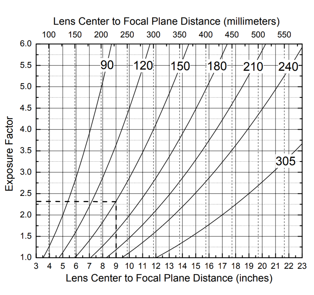
The diaphragm is f-numbered so that its closing or opening by one stop will require twice
as much or twice as less the amount of light reaching the film. At f/5.6, then the exposure
time should be twice as less as the exposure time required for taking pictures at f/8.
When the exposure time for f/5.6 is known, but lighting conditions require f/16, then the
exposure time is to be increased eight times, because the diaphragm has been closed by
three stops. Depth-of-field valuse at various f-numbers and distance settings are given
in the table.
Red dots are provided on the diaphragm scale between figures "8" and "11" and on the
distance scale between figures "10" and "5". When setting the diaphragm against these
dots, the image of objects arranged at a distance from 3m to infinity will be quite
sharp on the negative.
Distance scale settings in meters
Depth-of-Field, at aperture
f/4.5
f/5.6
f/8
f/11
f/16
f/22
inf
18.0 - inf
11.0 - inf
8.5 - inf
6.0 - inf
4.5 - inf
3.3 - inf
10
7.0 - 20.0
6.0 - 30.0
5.0 - inf
4.0 - inf
3.3 - inf
2.5 - inf
5
3.9 - 7.0
3.7 - 9.0
3.4 - 12.0
2.9 - 17.0
2.5 - inf
2.0 - inf
3
2.8 - 3.7
2.6 - 3.9
2.3 - 4.5
2.2 - 6.0
1.8 - 11.0
1.7 - 30.0
2.5
2.2 - 2.9
2.1 - 3.1
1.9 - 3.5
1.8 - 4.0
1.6 - 5.0
1.4 - 8.0
2.0
1.8 - 2.3
1.7 - 2.6
1.6 - 2.8
1.4 - 3.5
1.2 - 4.0
1.5
1.4 - 1.7
1.3 - 1.8
1.2 - 2.0
1.2 - 2.2
1.0 - 2.8
1.3
1.2 - 1.5
1.1 - 1.6
1.1 - 1.7
1.0 - 1.9
0.9 - 2.2
The flash bulb contact is intended to synchronize a flash of the bulb with a moment
of the shutter full opening.
When employing single-flash bulbs the shutter should be set for a speed of 1/10 sec. or
"B", when employing multi-flash bulbs the shutter may be set for any speed. The flash
bulb synchronizer operates automatically just after the shutter has been released.
Loading the Camera
Fig. 2 - Loading the Camera
1 - magnifier
2 - frame viewfinder back window
3 - viewfinder hood lock
4 - lock of camera side walls
5 - pressure plate
Shift the lock strap of side walls in the direction of the arrow as far as it
goes; first open the side wall which bears a strap and then the other wall.
Brake the seal of the film roll; insert the end fo the film protective paper
into the slit of the take-up spool and fold it; then by turning the film rewinding
knob, wind up 1-2 layers of the paper, the take-up spool being held to prevent the
film from unwinding.
Pull up the fastening knob of the take-up spool and place the spool with the
film into the socket making sure that the spool is set into the centre of the
socket, then put the fastening knob to the initial position. Make sure that the
paper tension is adequate, then first shut the side wall which bears the strap,
then replace the other side wall and shift the strap back to the stop.
Turn the window cover knob clockwise and rotate slowly the film advance knob
until the protective paper worning marks followed by a figure "1" appear in the
red window. Shut the window cover and the camera is ready for use.
Taking Pictures
Refer to tables or an exposure meter to determine an exposure, taking into account
film sensitivity, aperture selected, etc,. and set the shutter.
Set the aperture.
Open the viewfinder front panel.
Adjust the magnifier to working position.
Focus lenses for image sharpness.
Frame the shot by viewing it through the viewfinder.
Cock the shutters.
Release the shutters depressing the release lever or cable release.
Just after exposure, advance the film (lest you should forget). With this purpose,
turn the window cover knob and smoothly rotate the film advance knob until the
next odd numeral appears in the peep-window, then shut the window cover.
The camera may also serve for taking non-stereoscopic conventional pictures. In this
case one of the lenses should be tightly closed by a cap. To achieve convenience in
counting shots it is recommended to take pictures using the left lens. Count the
shots beginning from figure "1".
Unloading the Camera
Having taken six stereoscopic or twelve conventional pictures, advance the film protective
paper to the end. It may happen that when the film advance has almost come to the end,
the knob rotation would be detained by the paper jammed in the take-up spool slit; this,
however, will not prevent unloading the camera in the daylight.
To unload the camera, proceed as follows:
Shift the lock strap of the side walls in the direction of the arrow as far as it
goes and open the side walls of the camera.
Pull-up and slightly turn the film rewinding knob.
Take out the spool with the film retaining its tension, seal it up and safely store
it until developed.
Replace the take-up spool into its socket so that its upper face end iwth a notch
would be set against the film advance knob.
Shut the camera side walls and shift the lock strap to the initial position.
Printing Frame
The printing frame is designed for making from stereoscopic negative either a pair of
prints simultaneously or each print separately.
At simultaneous printing each stereoscopic pair should be cut; separate printing a
stereoscopic pair of prints with correct arrangement of images is obtained without cutting.
For conventional examination the prints should be mounted at the same level on a cardboard
of sixe 62x132 mm.
Simultaneous printing of the stereo pair is done as follows:
Cut 6x13 cm sheets of paper
Take off the removable cover
Turn the clamping spring and take out the cover.
Put the film on the glass with its emulsion side up.
Place the paper under the cover flat springs
Put the cover on the negative.
Turn the printing frame over, adjust the edges of the both negatives relative to
the frames and turning the clamping spring, fix the cover.
Expose both negatives.
To make a stereoscopic pair of prints separately, proceed as follows:
Cut 6x13 cm sheets of paper.
Mark each negative, from which the stereoscopic pair is composed, with figures "1"
and "2", put the figures in the intervals between the negatives (mark the negatives
starting from the first one).
Put on the removable cover having closed the right-hand frame.
Turn the clamping spring and take out the cover.
Put the film on the glass with its emulsion up, so that the left frame would
accomodate the negative marked with figure "2" (the film roll should be placed from
the right side of the frame).
Put the cover on the negative having laid the paper under the flat springs of the cover.
Turn the frame cover, adjust the negative edges relative to the frame and, having set
the clamping spring, fit the cover.
Expose the left-hand negative.
Shift the removable cover having closed the left-hand frame.
Release the clamping spring and shift the film so that the negative marked with
figure "1" would face the right-hand frame; see that the edges of the negative coincide
with those of the frame, and fix the cover.
Expose the right-hand negative.
Note: The left and right negatives are to exposed for equal length of time.
Stereo Viewer
The stereo viewer is designed for viewing stereoscopic pictures on a transparent and
non-transparent base. For viewing stereoscopic pictures on the transparent base provision
is made in the stereo viewer frame for two square openings.
The stereo viewer is put into the case in disassembled state. To assemble it, observe the
following sequence of operations:
Turn the block to the stop so that the guides are at an angle to the foot.
Fix the support frame on the cursor so that the pins with elastic washers come
through the holes of the support frame.
Screw up the stereoscopic spectacles to the guides using a plank as a screw-driver.
To dismantle the stereo viewer the same operation is repeated in reversed order.
To gain a stereoscopic effect, proceed as follows:
Place a stereoscopic picture into the frame.
Adjust the stereoscope according to your eyes by slowly moving the frame along
the guides until the best sharpness is achieved, both pictures merging into a
single three-dimensional image.
General Instructions
The stereo set pairs should be handled with care.
Keep the taking lenses clean, otherwise the picture quality may get worse.
Having breathed on the lens surface, wipe the taking lenses, stereo viewer lenses and the
frame glass only from outside using a clean linen rag or cotton.
Do not unscrew the mounts and do not take the lenses apart.
29-Mar-21 11:33 AM:
Lens Angle Equivalents
29-Mar-21 10:53 AM:
Brightness, Light Levels & EV
10-May-21 10:48 AM:
Wattage, Brightness, Light Levels & EV
Created by: (DB)Fotodiox Tech Support
Modified on: Mon, Jul 11, 2016 at 4:12 PM
Terminology
At last, viable LED light bulb for photography and videography have arrived on the scene. Now we are talking even lower power consumption for a comparable light output and the watt consumption numbers continue to go down. "Wattage" is no longer a valid reference point as that only refers to the amount of power a light draws, "Lumens" is the correct term as that measures light output.
Lumens is the stable measurement of light output that will not vary as LED light bulbs continue to get brighter and more efficient. So here are some numbers and charts for you to keep in mind when shopping for lighting. It won't be long before referencing incandescent bulbs is totally a thing of the past, so learn your lumen numbers now. Simply put, the higher the number, the brighter the bulb.
Lumens
The lumen (lm) is the SI derived unit of luminous flux, a measure of the total "amount" of visible light emitted by a source. Luminous flux differs from power (radiant flux) in that luminous flux measurements reflect the varying sensitivity of the human eye to different wavelengths of light, while radiant flux measurements indicate the total power of all electromagnetic waves emitted, independent of the eye's ability to perceive it.
Lumens are related to lux in that one lux is one lumen per square meter. The lumen can be thought of casually as a measure of the total "amount" of visible light in some defined beam or angle, or emitted from some source. The difference between the units lumen and lux is that the lux takes into account the area over which the luminous flux is spread. A flux of 1000 lumens, concentrated into an area of one square meter, lights up that square meter with an illuminance of 1000 lux. The same 1000 lumens, spread out over ten square meters, produces a dimmer illuminance of only 100 lux.
Electrical power equivalents for differing lamps
Light Output (lumens)
Electrical Power Consumption (watts)
Incandescent
Compact fluorescent
LED
200
25
3-5
n/a
450
40
9-11
6-8
800
60
13-15
9-12
1,100
75
18-20
13-16
1,600
100
24-28
18-22
2,400
150
30-52
30
3,100
200
49-75
32
4,000
300
75-100
40.5
EV / Lux / FootCandle Conversion
The unit is defined as the amount of illumination the inside surface of a one-foot-radius sphere would be receiving if there were a uniform point source of one candela in the exact center of the sphere. Alternatively, it can be defined as the illuminance on a one-square foot surface of which there is a uniformly distributed flux of one lumen. Thus one foot-candle is equal to one lumen per square foot or approximately 10.764 lux. In the motion picture cinematography field, incident light meters are used to measure the number of footcandles present, which are used to calculate the intensity of motion picture lights, allowing cinematographers to set up proper lighting-contrast ratios when filming.
EV / Lux / FootCandle Conversion Chart
EV
Lux
FC
EV
Lux
FC
-3
0.313
0.029
8
640
59.5
-2
0.625
0.058
9
1,280
119
-1
1.25
0.116
10
2,560
238
0
2.5
0.232
11
5,120
476
1
5
0.465
12
10,240
951
2
10
0.929
13
20,480
1,903
3
20
1.86
14
40,960
3,805
4
40
3.72
15
81,920
7,611
5
80
7.43
16
163,840
15,221
6
160
14.9
17
328,000
30,442
7
320
29.7
18
656,000
60,885
Exposure Value (Ev) & Corresponding Settings
Photography is all about capturing light, colors and moods. Photographs act as an imprint for all the beautiful moments or striking views perceived by human eye in its lifetime. This art of capturing moments and beauty, requires mastering the understanding of exposures. Exposure is a very basic and essential element in photography which helps in creating mood and envisioning the photographers perspective and viewpoint. The exposure is measured in Ev which stands for 'Exposure Value'. This chart relates lighting conditions to their exposure values, while this chart isn't much by itself it is a good indicator of the light levels.
Ev0 = f/1.0 at 1 second An Ev increase of 1 = halving of light admitted
Exposure Value Chart - Ev and Corresponding Shutter / Aperture Settings
F-Stop
Shutter
f/1
f/1.4
f/2
f/2.8
f/4
f/5.6
f/8
f/11
f/16
f/22
f/32
1 sec
0
1
2
3
4
5
6
7
8
9
10
1/2
1
2
3
4
5
6
7
8
9
10
11
1/4
2
3
4
5
6
7
8
9
10
11
12
1/8
3
4
5
6
7
8
9
10
11
12
13
1/15
4
5
6
7
8
9
10
11
12
13
14
1/30
5
6
7
8
9
10
11
12
13
14
15
1/60
6
7
8
9
10
11
12
13
14
15
16
1/125
7
8
9
10
11
12
13
14
15
16
17
1/250
8
9
10
11
12
13
14
15
16
17
18
1/500
9
10
11
12
13
14
15
16
17
18
19
1/1000
10
11
12
13
14
15
16
17
18
19
20
1/2000
11
12
13
14
15
16
17
18
19
20
21
1/4000
12
13
14
15
16
17
18
19
20
21
22
Exposure Value Equivalent Examples Chart
EV
Lighting Situation
EV
Lighting Situation
-6
Night, away from city lights, subject under starlight only.
6
Brightly lit home interiors at night. Fairs, amusement parks.
-5
Night, away from city lights, subject under crescent moon.
Night, away from city lights, subject under half moon. Meteors (during showers, with time exposure).
8
Las Vegas or Times Square at night. Store windows. Campfires, bonfires, burning buildings. Ice shows, football, baseball etc. at night. Interiors with bright florescent lights.
-3
Night, away from city lights, subject under full moon.
9
Landscapes, city skylines 10 minutes after sunset. Neon lights, spotlighted subjects.
-2
Night, away from city lights, snowscape under full moon.
10
Landscapes and skylines immediately after sunset. Crescent moon (long lens).
-1
Subjects lit by dim ambient artificial light.
11
Sunsets. Subjects in deep shade.
0
Subjects lit by dim ambient artificial light.
12
Half moon (long lens). Subject in open shade or heavy overcast.
1
Distant view of lighted skyline.
13
Gibbous moon (long lens). Subjects in cloudy-bright light (no shadows).
2
Lightning (with time exposure). Total eclipse of moon.
14
Full moon (long lens). Subjects in weak, hazy sun.
3
Fireworks (with time exposure).
15
Subjects in bright or hazy sun (Sunny f/16 rule).
4
Candle lit close-ups. Christmas lights, floodlit buildings, fountains, and monuments. Subjects under bright street lamps.
16
Subjects in bright daylight on sand or snow.
5
Night home interiors, average light. School or church auditoriums. Subjects lit by campfires or bonfires.
17-21
Rarely encountered in nature. Some man made lighting.